

3DR Radio 호환 텔레메트리 세트(915)
기술지원
기본적인 기술지원(기체조립/세팅, 픽스호크 기본 세팅/튜닝/트러블슈팅)을 위해 카페를 오픈 하였습니다. 정보공유카페 ’드론제어연구소’ 에서 회원 가입 하신 후 Q&A에 질의 하시면 가능한한 성심껏 답변 드리도록 하겠습니다.
Specifications:
- 6-position DF13 connector
- 100 mW maximum output power (adjustable)
- -117 dBm receive sensitivity
- Based on HopeRF’s HM-TRP module
- RP-SMA connector
- 2-way full-duplex communication through adaptive TDM
- UART interface
- Transparent serial link
- MAVLink protocol framing
- Frequency Hopping Spread Spectrum (FHSS)
- Configurable duty cycle
- Error correction corrects up to 25% of bit errors
- Open-source SIK firmware
- Configurable through Mission Planner and APM Planner
- Supply voltage: 3.7-6 VDC (from USB or DF13 connector)
- Transmit current: 100 mA at 20 dBm
- Receive current: 25 mA
- Serial interface: 3.3 V UART
LED 상태 설명
- 녹색 깜박임 – 피어 검색 중
- 녹색 점등 – 피어 연결 됨
- 적색 깜박임 – 데이타 전송 중
- 적색 점등 – 펌웨어 업데이트 모드
RF 파라메터 참고
- Baud (default 57) : the rate at which the mission planner or vehicle communicates with the local radio. “57” = 57600 bits per second.
- Air Speed (default 64) : the rate at which the two radios will communicate with each other. “64” = 64kbps (kilobits per second). Setting a lower rate will increase the range of the radio but reduce the rate of data (i.e. the amount of data that can be sent in a given time) across the link.
- ECC (default is “on”): controls whether error correction is on or off. When on “12/24 Golay error correcting code” is used which involves sending a 16 bit CRC byte along with the data to ensure that bad data is thrown away. Unfortunately this also halves the data rate across the link but it is recommended to leave ECC on especially when when the vehicle is far from home base because transmission errors increase greatly with distance.
- MAVlink (default is “MAVLink”) : this controls whether the transmission is optimised for MAVLink packets or not. Set to “Low Latency” if using a joystick or an android tablet’s virtual joystick to manually fly the vehicle. Note that information on the radio signal strength (rssi) and error rate is only sent if this parameter is set to it’s default, “MAVLink”.
- Tx Power (default 20) : the transmission power where 1=1.3milliWats, 2=1.5mW, 5=3.2mW, 8=6.3mW,11=12.5mW, 14=25mW, 17=50mW, 20=100mW. This should be set to conform with your local regulations. Some per-country information is below.
- Duty Cycle (default 100) : the maximum percentage of time that the radio will transmit packets. Some regions of the world allow for higher transmit power or more frequencies if you have a duty cycle below a given threshold. So for example in Europe you can transmit on a wider range of frequencies in the 433 band if your duty cycle is below 10%. Telemetry traffic is quite ‘bursty’, so the average transmit time is not generally high. When you set a duty cycle below 100% then your available bandwidth will be reduced, so you will find it will only work well for telemetry at higher air speeds. A radio can be set to receive only by setting it’s Duty Cycle to zero.
- Max Window (default 33) : ensure the GCS can send a packet to the vehicle ever 33msec. This should be kept as a low number (like 33) when the “MAVLink” setting is “Low Latency”
- LBT Rssi (default 0) : holds the threshold used for “listen before talk” which allows it to comply with some country’s regulatory requirements. When non-zero the radio listens for quiet period of time where no signals from other radios are received before transmitting. This parameter holds the receiver signal strength below which the airwaves are considered “quiet”. If this param is set to zero then LBT is disabled. Setting this to 25 (the min) is -121 dBm. Each increment above 25 raises the threshold by about 0.5dB so for example 40 equals a signal strength of 7.5dB. The full formula is:
signal_dBm = (RSSI / 1.9) - 127
The LBT implementation in the 3DR radio uses a minimum listen time of 5ms, plus randomised listen time as per the European 9.2.2.2 rules. Note that in many regions you need to implement LBT in conjunction with AFA (Adaptive Frequency Agility). The 3DR Radio implements AFA as long as you have
NUM_CHANNELSset to more than 1.
AT 명령어 세트
- ATI – show radio version
- ATI2 – show board type
- ATI3 – show board frequency
- ATI4 – show board version
- ATI5 – show all user settable EEPROM parameters
- ATI6 – display TDM timing report
- ATI7 – display RSSI signal report
- ATO – exit AT command mode
- ATSn? – display radio parameter number ‘n’
- ATSn=X – set radio parameter number ‘n’ to ‘X’
- ATZ – reboot the radio
- AT&W – write current parameters to EEPROM
- AT&F – reset all parameters to factory default
- AT&T=RSSI – enable RSSI debug reporting
- AT&T=TDM – enable TDM debug reporting
- AT&T – disable debug reporting
EEPROM Parameters 예 by ATI5 명령
- S0: FORMAT=22
- S1: SERIAL_SPEED=57
- S2: AIR_SPEED=64
- S3: NETID=25
- S4: TXPOWER=20
- S5: ECC=1
- S6: MAVLINK=1
- S7: OPPRESEND=1
- S8: MIN_FREQ=915000
- S9: MAX_FREQ=928000
- S10: NUM_CHANNELS=50
- S11: DUTY_CYCLE=100
- S12: LBT_RSSI=0
- S13: MANCHESTER=0
- S14: RTSCTS=0
- S15: MAX_WINDOW=131
AT명령어로 NETID 변경 하기
1. PC와 기체에 Radio를 켜고, PC 일반 터미널 프로그램을 실행하여 연결한다. 통신속도는 57,600bps
2. ’+++’을 입력 -> ’OK’ 응답이 나오면 command mode로 진입한 것임. 다음 순서로 명령어 실행
RTS3=25 (25는 변경할 NETID)
RT&W
RTZ
ATS3=25
AT&W
ATZ
3. 터미널을 종료한다. 이제 2개의 telemetry Radio는 NETID25로 서로 연결되었습니다.
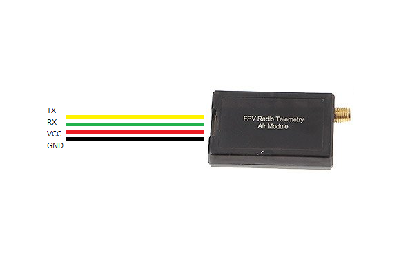
DF13 4Pin 배열(Wring)
The Telemetry Radio set includes:
- This product includes one radio unit and antenna, for use either in the air or ground
- 6-wire Pixhawk connector cable
- 6-to-5-position APM and PX4 connector cable


상품평
아직 상품평이 없습니다.